Computer simulation saves $15,000 by solving difficult mixing problem
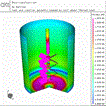
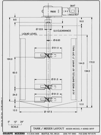
The chemical manufacturer was producing a highly-viscous latex polymer in a 107-inch diameter reactor with a total height of 172 inches and a liquid height of 138 inches. Material A is charged to the reactor. A relatively small amount of material B, depending on the final viscosity required by the product specification, is added as a thickener. Since B has a low pH, aqueous ammonia is added to keep the pH above 8. If the pH is not kept high enough, the material will not thicken to the required high viscosity levels. The viscosity of B is less than 10 centipoise and may be diluted with water. A has a viscosity of 150 centipoise. As the batch thickens, addition B and ammonia float to the top and create localized lumps of highly viscous material that are hard to blend out. The purpose of the mixer is to rapidly mix the additions of B and ammonia into A without entraining air. Air entrainment will negatively affect the specified density of the material, which is slightly above water.
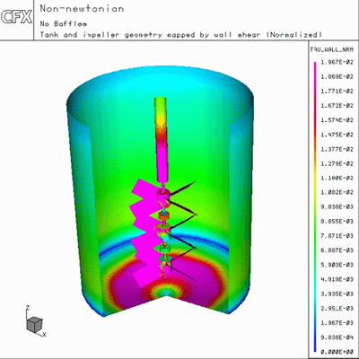
Original mixer design
The proprietary nature of the ingredients made it impossible to release samples to the company that was contracted to supply the mixers. Instead, they were asked to design the mixer for a viscosity of 50,000 centipoise. Sharpe engineers designed a mixer that should have worked well under the specified conditions. It features three axial impellers, two at 51 inches in diameter and one at 38 inches. The 40 horsepower motor was designed to operate at 1750 rpm and included a 27:1 gearbox to bring the speed down to 65 rpm. Laboratory tests were performed on a material that matched the specifications provided by the chemical manufacturers and seemed to show that the mixer would work well. However, when it was installed, problems soon appeared. Operators reported that they weren't achieving the desired level of mixing, a condition known as batch control where the material was moving throughout the vessel. Because of this problem, the company was unable to run the reactor at full capacity and also could not run higher viscosity grades of the material.
The chemical manufacturer called in the company that built the mixer and asked them to fix the problem as quickly as possible. Their original thought was that it would be necessary to install a larger mixer that would be capable of handling the highly-viscous material. "We suggested moving in a different direction," said Steven Drury, director of applications for Sharpe Mixers. "We noticed that the motor drew considerably less horsepower than we were expecting. We suspected that we might be dealing with a shear-thinning material whose viscosity significantly decreased as it encountered the impeller blades." A shear thinning material, is one that first shows solid-like behavior but yields to a less resistant state. When subjected to sheer, some materials show as much as a million-fold drop in viscosity over a very small region of increasing shear stress. Examples include toothpaste, Carbopol and Ketchup.
Need to verify new approach
"Of course, we couldn't suggest to the customer that they make a design change based on a hunch," Drury continued. "We needed to verify that our thinking was correct. The customer helped by creating a material that they promised would behave exactly like the one in the reactor, even though it did not have the exact same chemical properties." Sharpe engineers tested the material in an LVF-4 viscometer from Brookfield Engineering. The tests showed a viscosity of 151,000 centipoise at 6 rpm, 83,000 centipoise at 12 rpm, 39,600 centipoise at 30 rpm and that viscosity dropped below the limits of the instrument at 60 rpm. These results confirmed Drury's hypothesis but still left him a long way from a satisfactory solution.
"We needed to develop a new design and prove it would work before interrupting the customer's production," Drury said. One approach would have been to build an experimental model of the tank. But in this case Sharpe had only a small sample of material. Another problem with this approach is that the model has to be scaled to keep its cost reasonable and scaling causes errors that are very difficult to estimate. Any changes to the model, which would be required to investigate alternative configurations, would take additional time and money. Another problem with this approach is that viewing an experiment of this type would give a good general idea of how the two fluids mix but would not provide any quantitative results.
Decision to use CFD
So Drury decided to address the problem through a CFD analysis. CFD provides fluid velocity, pressure and species concentration values throughout the solution domain for problems with complex geometries and boundary conditions. As part of the analysis, an engineer may change the geometry of the system or operational conditions such as inlet velocity, system geometry, etc. and view the effect on fluid flow patterns or concentration distributions. CFD also can provide detailed parametric studies that can significantly reduce the amount of experimental work necessary to develop prototype equipment and thus reduce design cycle times and costs.
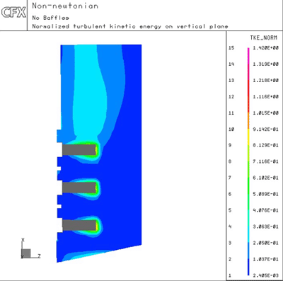
Sharpe had previously selected CFX software from AEA Technology, Bethel Park, Pennsylvania, because it is specifically designed to address mixing problems. CFX-ProMixus is an interactive software tool that provides detailed three-dimensional analysis of mixing processes in batch reactors. Starting from an intuitive GUI, the user specifies reactor configurations from lists of tank, baffle and impeller templates. CFX-ProMixus then automatically performs a CFD simulation of the flow within that vessel. The output is presented in a gallery of graphics and tables that illustrate and quantify mixing performance.
Simulation solves the problem
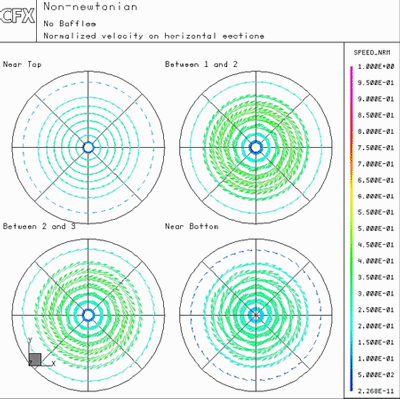
Drury began by modeling the original configuration using the properties generated in the laboratory tests. The model predicted the dead spots that were seen in the reactor. Because the viscosity was lower at the impellers due to the sheer thinning properties at the impellers, Drury felt that the speed and size of the turbine could be increased to improve mixing efficiency without exceeding the torque limits of the existing motor. He ran a series of iterations in which he tried different motor speeds and impeller configurations. For each iteration, he viewed the results of the simulation to evaluate the motion of the fluid throughout the tank as well as the amount of torque required to drive the mixer. He found that replacing the small turbine at the bottom of the tank with a full-scale turbine and increasing the speed of the impeller from 60 to 118 rpm provided complete mixing. Drury found that additional improvements could be achieved by removing the baffles that had been added to the tank, or for better results, he recommended that the existing baffles be replaced with adjustable baffles that could be disengaged for shear thinning products and extended for products with lower viscosity.
"We invited the customer in to view the simulation," Drury said, "and they were very impressed with what they saw. We showed them how the mixer would have worked well if the original material specifications had been correct and how the simple and inexpensive modification of increasing impeller size, increasing motor speed and disengaging the baffles would provide the batch control they were seeking under the actual conditions in the reactor. We changed out the impeller and a few gears in the speed reducer. The customer made the modifications that we suggested to the baffles. The results on the plant floor matched the simulation perfectly. The attitude of the customer has changed from being frustrated to being thrilled. In fact, they are so happy that they have since ordered three more identical mixers."
For more information, contact AEA Technology: CFX, Omega Corporate Center, 1260 Omega Drive, Pittsburgh, PA 15205. Phone: 412-893-1005, FAX: 412-893-1030. E-mail: info@engsw.aeat.com. World Wide Web: http://www.cfx.aeat.com
Subscribe to our free e-mail newsletter.
Click for a free Buyer's Guide listing.
