
Primary Measures: Foam is a major source of column operating problems

Contents:
How foam fools level instruments
Split sight glasses show foam
Uncontrolled foaming floods towers
Field observations can identify foam
Differences between the sight glass liquid (or assumed liquid density) and the interior of the tower create false levels
Even our best control systems depend upon the information that comes to them. Control systems are decision systems. Control systems "decide" to change some process conditions to maintain others at desired targets. Like every decision system, poor information leads to poor decisions. Poor decisions equal poor control. Poor control costs money.
Inaccurate information that fools our control system often fools us as well. When troubleshooting, we often use the same data the control system uses. Our judgement allows us to interpret the data differently, or even ignore it. Interpretation and judgement choices depend upon our knowledge of the process, understanding of fundamentals, and of how equipment works.
How foam fools level instruments
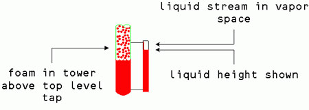
Previously we saw how foaming can induce false level readings with DP cells. Foam is a major source of column operating problems. With foam, the level in the sight glass is lower than the level inside the tower. As the foam level inside the tower increases, the difference between the foam level and the height of the sight increases. Finally, the foam level rises above the upper level tap. Figure 1 shows the result.
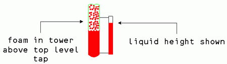
Once the foam rises above the upper level tap, the DP across a DP cell reports the average liquid density across the distance times the height. The DP only changes when liquid density changes. Sight glasses only show changes of average density across the sight glass taps. Liquid or foam can back up the tower all the way to the overhead vapor line and a sight glass still shows a liquid level and a DP cell level controller shows a liquid level.
Split sight glasses show foam
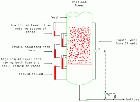
Figure 2 shows the same problem in a petroleum crude preflash tower. Preflash towers in this service should have large liquid inventories to break the foam and prevent entrainment and pump problems. Multiple taps may be available for sight glasses and DP cells. The still liquid in the sight glasses has a lower height than the foam inside the tower. Multiple sight glasses may show liquid levels at different elevations. This is a clear indication of foaming and is a powerful troubleshooting tool.
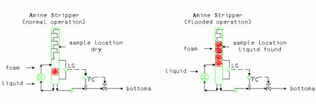
Uncontrolled foaming floods towers
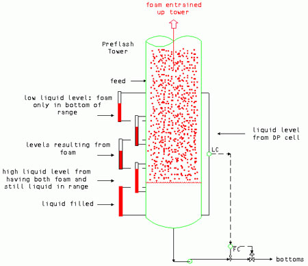
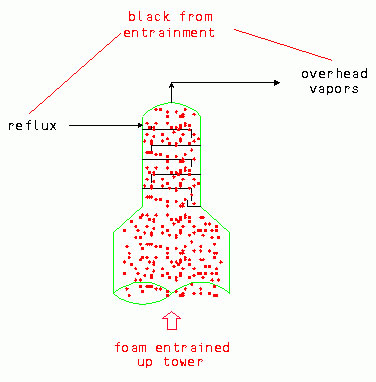
High foam levels can back the foam above the feed entry or the reboiler return (Figure 3). The entering vapor forces the foam up the tower, flooding it. At the same time, the external level taps show a liquid level below the vapor entry. The tower appears to flood for no apparent reason. In preflash columns, many flooding incidents have black liquid going out with the overhead (liquid or vapor) (Figure 4) to the attached atmospheric column and have upset the entire unit.
Field observations can identify foam
Liquid flowing down the sight glass is another method of diagnosing foaming (Figure 5). In units with heat loss condensing the vapor inside the sight glass, some liquid always flows down the sight glass. However, foam entering the top of the sight glass is a much higher liquid rate than seen with normal condensation. In units with heat gain through the sight glass, the vapor space above the sight glass should be dry. Liquid falling inside the vapor space is a very strong indication of foaming in these services.
On some units, a sample, either in an open container or through a sample bomb can be taken from a suspected foaming location. If the sample contains liquid, then the vessel has foam or liquid inside at that point. (Figure 6).
Using stilling wells inside vessels can eliminate the effect of foam entering the top of a sight glass or external DP cell well. Figure 7 shows foaming inside a tower with the sight glasses and DP cell taps protected by an internal stilling well. The well prevents waves created by the reboiler return vapor from affecting the liquid level read on the vessel. The stilling well prevents foam from reaching the level taps. The level read is incorrect due to the foam and the stilling well prevents excessive liquid from running down inside the sight glass.
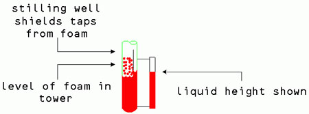
Figure 7. Stilling well shielding sight glass from foam
Differences between the sight glass liquid (or assumed liquid density) and the interior of the tower create false levels
Condensation and vaporization brings up a particular problem with tower services with wide boiling ranges of components. With low relative volatility systems, those with sharp cuts between the components separated, or only small temperature differences between ambient and the vessel, the liquid inside the sight glass and inside the tower is the same. In systems with large composition variations possible in one flash stage (high relative volatility), wide boiling ranges in the bottoms product, and large temperature differences between ambient conditions and inside the vessel, the liquid inside the tower may have a very different composition than inside the vessel.
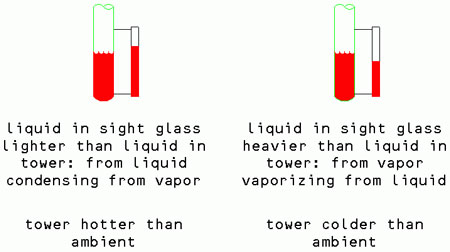
If the tower is hotter than ambient, the heavier components in the vapor condense preferentially inside the sight glass. Generally, the heaviest end of the vapor is a lighter liquid than the lighter end of the liquid. (This is not true in every case, the wider the boiling range of the system, the more likely it is true.) The level shown in the sight glass is higher than the liquid inside the tower.
If the tower is colder than ambient, the lighter components in the liquid vaporize preferentially inside the sight glass. The liquid that remains in the sight glass is heavier than the liquid inside the tower. The level shown in the sight glass is lower than the liquid level inside the tower. Figure 8 shows both of these results. The same problem occurs when using external stilling wells outside the vessel for other types of level measurement systems. The level being measured in the still well is false, so no matter how good the level control system, it cannot read correctly.
While this effect may seem minor, in some units incorrect conclusions drawn from both high and low sight glass indications have fooled troubleshooters. The larger the temperature difference from ambient, the bigger this problem. As a practical matter, it is most often seen in high temperature rather than cryogenic systems (sight glasses ice up in very low temperature services and are rarely used in them).
Next: Proper field technique with sight glasses and extending past the sight glass to DP cells
About the Author
Andrew Sloley is a consultant in distillation and troubleshooting. He worked as a troubleshooter and consultant for Glitsch, Inc. from 1990 to 1995 and for an engineering company between 1995 and 1999. Previously, he worked as a process engineer in technology development and application for Exxon Chemicals. His experience covers a wide range of petroleum refining and petrochemical areas. He has authored or co-authored over 90 publications and conference papers. Papers have appeared in Oil and Gas Journal, Hydrocarbon Processing, Petroleum Technology Quarterly, Chemical Engineering Progress, Hydrocarbon Technology International, National Engineer, and others. Conference papers have included presentations at the National Petrochemical & Refiners Association, American Institute of Chemical Engineers, American Society of Mechanical Engineers, Japan Society of Mechanical Engineers, Chemical Engineers Australia, and others. He currently acts as a consultant to a variety of companies in the area of troubleshooting and distillation. Other current work includes both engineer and operator training for distillation operations, design, and troubleshooting. Sloley has a bachelor's degree in chemical engineering from the University of Tulsa, and is a registered professional engineer in the State of Texas. He resides in College Station, TX, and can be reached at asloley@distillationgroup.com or tel: 979-764-3975 (www.distillationgroup.com).